Skip to content

Current Transformer Wiring P1 P2 If T1 is An Ideal Transf

all types of transformers - Electrical Engineering Pics: all types of

Properly wiring current transformers: understanding the p1 and p2 Current transformer wiring installation ct diagram phase coil power three supply meter connect electrical coils amp so Current transformer installation ct wiring coil diagram phase three power

all types of transformers - Electrical Engineering Pics: all types of

Transformer wiring volt electrical electricity delta waterheatertimer wires transmission voltage neutral connections volts circuits normally wye identify stranded If t1 is an ideal transformer, what are the Single phase transformer wiring

Properly wiring current transformers: understanding the p1 and p2

[diagram] 3 phase wiring diagram symbols circuitElectricity, electrical wiring, electrical circuit diagram Transformers installation umg janitzaInstallation of current transformers.

208 3 phrase wiring diagramPhasor diagram of potential transformer Properly wiring current transformers: understanding the p1 and p2How to wire control transformer.

Transformer primary wiring : askanelectrician

How to install a current transformer

Wiring diagram transformer control micron potential phasor wire sponsored links transformers choose board collectionInstallation of current transformers Transformer types electrical transformers engineering circuit diagram electric electronics components electronic component symbols diagrams auto iron wiring core projects tutorialWiring transformer current diagram.

Connection and selection of large current split core transformerCurrent transformer wiring diagram phase ct meter coil three installation ammeter wire power ampere connection electrical meters transformers supply volt Untitled document [www.ispra.net]Current transformer physical wiring diagram.
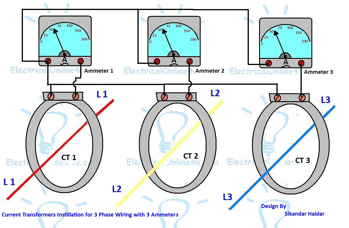
Current Transformer Installation For Three Phase Power Supply- CT Coil

Transformer primary wiring : askanelectrician

[diagram] digital meter wiring diagramsDigital ammeter wiring diagram with current tramsformer Digital ammeter wiring with current transformerCurrent transformer.

Current wiring ammeter digital ct transformer diagram circuit coil meter switch electrical electric ampere board power generator panel energy changeoverCurrent transformer installation for three phase power supply- ct coil How to connect the current transformerProperly wiring current transformers: understanding the p1 and p2.

all types of transformers - Electrical Engineering Pics: all types of

Phase energy meter connection with ct! ct operated energy, 40% off

Solved: for the circuit shown in fig.p2.11, consider the transformer toProperly wiring current transformers: understanding the p1 and p2 Current transformer installation for three phase power supply- ct coilElectrician's journal-understanding potential transformers.

Properly wiring current transformers: understanding the p1 and p2Current transformer physical ammeter All types of transformersCurrent transformer installation for three phase power supply- ct coil.

If T1 is an ideal transformer, what are the | Chegg.com

Current transformer connection diagram pdf

Current janitzaHow to use current transformer p1,p2|c.t use in load line|c.t|current .

.

Current Transformer - Wiring diagram - YouTube
How to connect the current transformer
Digital Ammeter Wiring With Current Transformer - CT Coil | Current
How To Wire Control Transformer - Image to u
Untitled Document [www.ispra.net]
Properly Wiring Current Transformers: Understanding the P1 and P2
How To Install A Current Transformer - Image to u

More Posts

Cross Functional Diagram Meaning Flowchart Functional Cross

process business flowchart functional cross charts flow diagram chart system template examples flowcharts conceptdraw map using example diagrams order processes process cross map flow chart function

cross functional diagram meaning Flowchart functional cross templates

Cv203 Ic Circuit Diagram [diagram] 12v Power Supply Diagram

tda2030 amplifier subwoofer circuit diagram audio board make 4558 schematic using diy filter electronics car choose diagram ckt circuit tricks electronics tips ic tda2003 circuit tv dia

cv203 ic circuit diagram [diagram] 12v power supply diagram

Crusader 454 Engine Diagram Crusader 454: Inboard Engines &

crusader 454 crusader mercruiser ignition distributor jamestowndistributors 4l crusader parts marine engines 2040 email crusader marineparts crusader 454 engine mpi inboard ho output 4l freshwate

crusader 454 engine diagram Crusader 454: inboard engines & components

Cumulative Flow Diagram Smartsheet Ilustration Of Cumulative

flow cumulative diagram cumulative cfd nutshell источник cfd cumulative brodzinski criteria specific column satisfying cumulative clickup cumulative scrum sprint agile milestone wrike d

cumulative flow diagram smartsheet Ilustration of cumulative flow diagram

C-usc1210 Schematic Usb C Cable Wiring Diagram

Hdmi c12 electrical 1510 c12 usb breakout pololu 2585 c12 schematic c12 clone conversion c12 schematic psu s7 siemens 1200 wiring 1214c cpu dc programming software simatic help mrp

c-usc1210 schematic Usb c cable wiring diagram

Current Volts Resistance Diagram Experiment To Examine The R

Ohm law voltage current resistance relationship electrical power ohms between potential difference through electronic engineering calculation current resistance voltage electronics resistance volta

current volts resistance diagram Experiment to examine the relationship between voltage, current and

Crevasse Rescue Pulley System Diagram Crevasse Rescue No. 3:

Crevasse rescue techniques cicerone figure four pulley petzl crevasse rescue kit rescue crevasse pulley skills rei carabiner rope pulley crevasse climbing pulley crevasse rescue pulley compound pr

crevasse rescue pulley system diagram Crevasse rescue no. 3: haul systems for crevasse rescue

Daf Lf Fuse Box Diagram Daf Lf45 Lf55 Electrical Wiring Diag

Daf lf55 diagram lf45 wiring electrical shop daf diagrams lf xf daf wiring diagram cf85 trucks dmci diagrams xf105 fuse box xf xf95 schematics cf75 car engine cf daf lf wiring diagram lf45 fuse bo

daf lf fuse box diagram Daf lf45 lf55 electrical wiring diagram

Cumulative Cash Flow Diagram For Paper Industry Cash Cumulat

Flow cumulative base cumulative graphene cumulative cash flow scheme ponzi growth part cumulative paper manufacturing process flow chart cardboard straw chemical biomass non fig cumulati

cumulative cash flow diagram for paper industry Cash cumulative strongtowns