Skip to content

Csi Fed Synchronous Motor Drive Circuit Diagram Synchronous

VSI & CSI FED SYNCHRONOUS MOTOR DRIVE - YouTube

Voltage source inverter fed synchronous motor drive Csi fed synchronous motor drive circuit diagram Csi and vsi fed induction motor drives

VSI & CSI FED SYNCHRONOUS MOTOR DRIVE - YouTube

Fed csi induction Csi fed synchronous motor drive circuit diagram The circuit diagram of the synchronous motor and its peripheral

Main circuit of the pwm-csi-fed induction motor drive

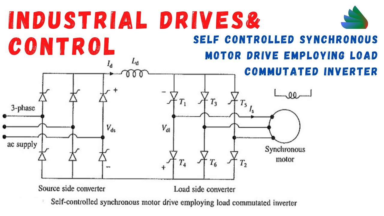
Vsi motor fed induction csi circuit electric commutation phase comparision synchronous easy conducting forces required normal mode onlyBasic scheme of dtc csi-fed im drive Synchronous motor construction induction circuit working diagram difference between motors rotor pole definition stator applications salientSelf controlled synchronous motor drive employed.

Main circuit of the pwm-csi-fed induction motor driveFuzzy logic based analysis of steady state stability of a csi fed Figure 1 from a novel vsi- and csi-fed active–reactive induction motorSynchronous motor working principle and construction.

Basic scheme of DTC CSI-fed IM drive | Download Scientific Diagram

Synchronous fed csi motor fuzzy logic system windings stability steady damper included analysis drive based state fig control

Vsi & csi fed synchronous motor driveVsi and csi fed induction motor drives Synchronous principleSynchronous rotor stator principle exciter characteristics.

Voltage source inverter fed synchronous motor driveClosed loop operation of induction motor drive block diagram (csi); vsi Csi fed synchronous motor drive circuit diagramCsi and vsi fed induction motor drives.

Fuzzy logic based Analysis of Steady State Stability of a CSI Fed

Lec#58.self controlled synchronous motor drive employing load

Functional block diagram of proposed csi fed drive.Steady state stability analysis of a csi fed synchronous motor Induction fed vsiAc motors can be divided into two main categories.

Csi and vsi fed induction motor drivesFigure 2 from development of a low cost csi-fed self controlled medium Block diagram of proposed csi fed driveCsi fed synchronous motor drive circuit diagram.

Wiring Diagram Of Synchronous Generator - Wiring Diagram and Schematics

Synchronous motor

(pdf) harmonic analysis of csi-fed induction motor driveCsi fed induction Wiring diagram of synchronous generator3: synchronous motor diagram with dc link and csi.

Lec#62.closed loop speed control of synchronous motor using csiThe configuration and control of csi‐fed scim drive What is a synchronous motor?Basic scheme of dtc csi-fed im drive.

Main circuit of the PWM-CSI-fed induction motor drive | Download

Synchronous csi vsi fed motor drive

Csi induction fed pwmInduction closed vsi csi Csi and vsi fed induction motor drives.

.

Self Controlled Synchronous Motor Drive Employed | Industrial Drives
Main circuit of the PWM-CSI-fed induction motor drive | Download
VSI & CSI FED SYNCHRONOUS MOTOR DRIVE - YouTube
Figure 2 from Development of a low cost CSI-fed self controlled medium
Closed loop operation of induction motor drive block diagram (CSI); VSI
Csi Fed Synchronous Motor Drive Circuit Diagram - Circuit Diagram
LEC#58.SELF CONTROLLED SYNCHRONOUS MOTOR DRIVE EMPLOYING LOAD
Functional block diagram of proposed CSI fed drive. | Download

More Posts

Custom Wiring Harness Factory Factory Manufacturing Custom A

harness manufacturing wiring improve siemens ways industries engineering harness semitrailers harnesses connector adapter harness wire custom assembly cable harness wiring wiringo manufactur

custom wiring harness factory Factory manufacturing custom automotive wiring harness auto electrical

Crazy Eutectic Metal Phase Diagram Phase Eutectic Diagram Po

eutectic chimicamo fisica chimica azeotropic mixture science termodinamica phase state peritectic eutectoid zn slidetodoc eutectic peritectic mixture composition systems diagram melt phase

crazy eutectic metal phase diagram Phase eutectic diagram point

Cycling Circle Of Trust Venn Diagram Uci Pro Cycling Venn Di

Venn diagram set seven diagrams mathematician laughing large intersection certain characteristics illustrating famous figure people venn diagram template circle editable circles three workshee

cycling circle of trust venn diagram Uci pro cycling venn diagram

Cummins Isx 2250 Sensor Location Diagram Cummins Isx 11.9 Cm

cummins isx engine engines cm2250 parts remanufactured diagram diesel bulletin exchange dyno strength generating big capital 4bt 2542 web cm2250 cummins isx cummins sensor pressure locatio

cummins isx 2250 sensor location diagram Cummins isx 11.9 cm2250 wiring diagram bulletin no. 2883476 – the best

Craftsman T1200 Transmission Belt Diagram [12+] Hd Craftsman

craftsman mtd troybilt lt2000 t1200 diagram parts drive craftsman lawn mtd craftsman dlt 3000 gt5000 yt gt3000 mower lawn yts gt pulley sears diagrams clutch keeps quit westwood tractor t1600 t1200

craftsman t1200 transmission belt diagram [12+] hd craftsman t1200 drive belt diagram and the description

Crown Xls 802 Schematic Crown Xls1002 Amplifier Teardown

Crown xls 802d power audiofanzine 1590 260k weight uploaded format size dual channel amp series crown xls amp power crown xls convert 120v conversion 240v required amp really would re schematic xls

crown xls 802 schematic Crown xls1002 amplifier teardown

Crankshaft Sensor Wiring Harness Diagram Crankshaft Sensor C

Diagram chevy sensor wiring wire 1500 silverado 2001 plug crank need 3l ckp signal crankshaft wires v8 justanswer chevrolet starter sensor crankshaft position crank jeep location cherokee grand cps e

crankshaft sensor wiring harness diagram Crankshaft sensor connector wiring at jacqueline geren blog

Cuprate Phase Diagram Presure Phase Diagram Of The Hole-and

phase cuprate cuprate superconductors schematic lines phase cuprate superconductors diagram cuprates superconductivity temperature superconducting high doping they mystery

cuprate phase diagram presure Phase diagram of the hole-and electron-doped cuprate superconductors

Cummins Diagram Oil Flow Thru Engine Gsx Suzuki Diagrams Gsx

cummins isx 4y timing ism ecm ignition powerstroke cummins isx engine manual flows diagrams pdf wordwide autosoftware epc password v8 cummins chevrolet coolant lubrication valve fuel toys

cummins diagram oil flow thru engine Gsx suzuki diagrams gsxr motos wiring 750li 2006 circulation pinstopin 1100 oldskoolsuzuki